Introduction
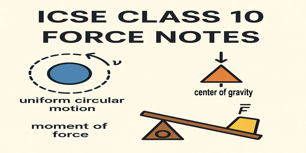
Understanding Force is a vital part of ICSE Class 10 Physics. In this chapter, students learn about the nature, types, and effects of force in everyday life. This blog provides ICSE Class 10 Force Notes that include key concepts, formulas, solved numericals, and frequently asked questions. Let’s dive into the Force Chapter Class 10 ICSE in a simplified and exam-ready format.
Study Support by Rohit Academy
Rohit Academy offers expert-curated ICSE Class 10 Physics Study Materials including ICSE Force Chapter Notes, diagrams, and key formulas for better understanding.
Study materials related to chapter 1
| Class 10 Chapter 1 Force Ex 1(A) Solutions |
| Class 10 Chapter 1 Force Ex 1(B) Solutions |
| Class 10 Chapter 1 Force Ex 1(C) Solutions |
| Class 10 Chapter 1 – Force Previous Year Questions |
Section A : Moment of force and Equilibrium
Force
- Force is a physical cause which changes or tends to change state of rest or motion or direction of a body. It can also change the shape or size of a body.
- Force is a vector quantity.
- S.I. Unit : Newton (N).
- C.G.S. Unit : dyne
- Gravitational unit : gf or kgf; Where, 1 kgf = 9.8 N.
Contact and Non-Contact
Forcesare the two main types of forces.
- Contact Force : Contact forces arise due to physical contact between two bodies.
Example : frictional force, tension, Buoyant Force etc. - Non-Contact Force : Non-contact forces arise due to attraction or repulsion between two bodies, i.e, there is no physical contact between them.
Example: gravitational force, electrostatic force, Magnetic Force etc.,
Motion
It is the change of position of an object with respect to time.
We have two kinds of motion :-
- Linear or translational motion : When a force acts on a stationary rigid body which is free to move, the body starts moving in a straight path in the direction of force. This is called Linear or translational motion.
Example : A object moving in a straight line, bullet fired from a gun.
- Rotational motion : When a force applied on fixed point of a body which is pivoted at a point, then body is starts rotating about that point. This is called a rotational motion.
Example : Motion of wheel, gears, motors, etc is rotational motion.
Moment (Turning Effect) of a force / Torque
- The turning effect of force acting on a body about an axis is called the moment of force.
- The moment of a force defined as the product of the force and the perpendicular distance from the axis of rotation to the line of action of the force.
- Moment of force = Force × perpendicular distance
Torque = F × ⊥ d
F1 x d1 = F2 x d2
The factors affecting the turning effect of a body are:
- Magnitude of the force applied
- Perpendicular distance from the axis of rotation
Units of moment of force
- S.I. unit : Newton meter (Nm).
- C.G.S. unit : dyne cm.
- Moment of force is a vector quantity.
Relationship between the SI unit and CGS unit of moment of force
\(⇒\ 1\ N\ =\ 10^5\ dyne\)
\(⇒\ 1\ m\ =\ 10^2\ cm\)
\(⇒\ 1\ Nm\ =\ 10^5\ dyne\ \times\ 10^2\ cm\)
\(⇒\ 1\ Nm\ =\ 10^7\ dyne\ cm\)
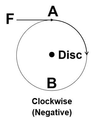
Clockwise moment
- If the force rotates the body in the clockwise direction then the moment is said to be the clockwise moment.
- A clockwise moment is taken as negative.
- It causes inward motion.
Anticlockwise moment
- If the force rotates the body in the anti-clockwise direction then the moment is said to be the anticlockwise moment.
- An anticlockwise moment is taken as positive.
- It causes outward motion.

Direction of rotation of a body can be changed by two ways :
- By changing the point of application of force.
- By changing the direction of force.
Common example of moment of force
- To open or shut a door, we apply the force at the free end of it because larger perpendicular distance, less force is needed to open or shut the door.
- The stone of hand flour grinder is provided with a handle near its rim because by applying small force at the handle it can be rotated easily about the iron pivot at its centre.
- It is easier to turn the steering wheel of a large diameter than that of a small diameter because less force is applied on steering of large diameter which is at a large distance from the centre of rim.
- To turn the rear wheel of a bicycle anticlockwise, a small force is applied to a large toothed wheel using the foot pedal. This wheel is connected to the rear wheel by a chain, and because the force is applied far from the center, it makes turning easier.
- A spanner (or wrench) has a long handle to produce larger turning moment so that nut can easily be turned with a less force.
- A jack screw used to lift a heavy vehicle is designed with a long arm so that it requires less force to rotate and raise or lower the vehicle.
***Note
- Larger the perpendicular distance, less the force required to produce the same turning effect.
- We can increase the moment of force by increasing the perpendicular distance of the force from the axis of rotation.
- We can reduce the moment of force by decreasing the perpendicular distance of the force from the axis of rotation.
Couple
Two equal and opposite parallel forces, not acting along the same line, form a couple. A couple is always needed to produce the rotation.
Example : turning a key in a lock, turning a steering wheel, turning a water tap.
Moment of couple
- Moment of couple is product of either force and the perpendicular distance between the two forces.
- A body is acted upon by two equal and opposite forces, that are NOT along the same straight line. The body will produce rotational motion.
- Moment of couple = Either force × perpendicular distance between two forces
- S.I. Unit : Newton meter (Nm)
- C.G.S. Unit : dyne cm
- Moment of couple is a vector quantity.
***Note
If a body is acted upon by two unequal forces in opposite directions, but not in the same line. The body will have both rotational as well as translational motion.
At A and B two forces, each of magnitude F is applied, which are equal and opposite forces. The two forces rotate the bar in anticlockwise direction. AB is the perpendicular distance between two forces which is called the coupling arm.

Moment of force F at the end A
= F × OA (anticlockwise)
Moment of force F at the end B
= F × OB (anticlockwise)
Total moment of couple = F × OA + F × OB
= F × (OA + OB)
= F × AB
= F × d (anticlockwise)
Total moment of couple = Either force × perpendicular distance between the two forces (or couple arm)
Equilibrium
When several forces acting on a body produce no change in its state of rest or motion, the body is said to be inequilibrium.
(i) Static equilibrium : When a body remains in the state of rest under the influence of several forces, the body is said to be in static equilibrium.
Example :
(a) A book lying on a table
(b) Beam balance in horizontal balance
(c) Book on the table
(ii) Dynamic equilibrium : When a body remains in the same state of motion under the influence of several forces, the body is said to be in dynamic equilibrium.
Example :
(a) A rain drop reaches the earth surface with a constant velocity.
(b) Aeroplane moves at the constant height
(c) Stone tied at the end of the string
(d) Revolution of moon around the earth
Conditions for equilibrium
The two conditions for a body to be in equilibrium are :
- The sum of all forces acting on the body must be zero.
- Algebraic sum of moments of all forces acting on the body about a point of rotation must be zero.
Principle of moments
- When a body is in equilibrium, the sum of the clockwise moments about a pivot is equal to the sum of the anticlockwise moments about the same pivot.
- sum of anticlockwise moments = sum of clockwise moments
- Example : A beam balance (physical balance) works on the principle of moments.
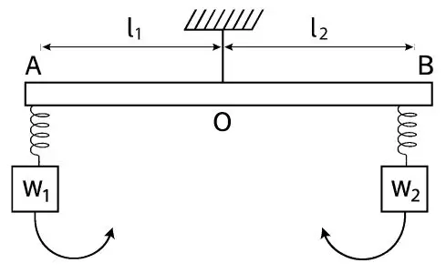
Let the distance of the weight \(W_1\) from the support be \(l_1\) and the distance of weight \(W_2\) from the support be \(l_2\). Let the weight \(W_1\) tries to rotate the scale in anti-clockwise direction. Then,
Anti-clockwise moment \(=\ W_1\ \times\ l_1\)
Clockwise moment \(=\ W_2\ \times l_2\)
According to the principle of moments,
Sum of the anticlockwise moment \(=\) Sum of the clockwise moment
Moment of load about the fulcrum \(=\) Moment of effort about the fulcrum
Load × Length of Load arm \(=\) Effort × Length of Effort arm
\(W_1\ \times\ l_1\ =\ W_2\ \times\ l_2\)
Section B : Centre of gravity (CG)
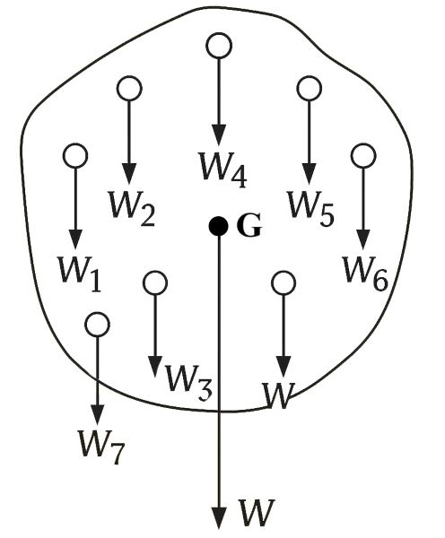
The centre of gravity of a body is defined as the point about which the algebraic sum of moments of weights of particles constituting the body is zero and the entire weight of the body is to act at this point.
***Note
- The position of the centre of gravity of any body will depend on the shape or distribution of mass of the body. It changes if the shape of the body is deformed.
For example, the centre of gravity of a uniform wire is at the middle of its length. But if the same wire is bent into the form of a circle, its centre of gravity will then be at the centre of the circle.
- It is not necessary that the centre of gravity always be within the material of the body.
Example : The centre of gravity of a ring or a hollow sphere lies at its centre where there is no material.
- The centre of gravity of a body is the position from where the net weight of the body is going to act.
The position of centre of gravity determines the stable equilibrium of the body.
Lower the position of centre of gravity, the body will be more stable.
- Centre of Gravity and balance point
When a body is freely suspended from a point, it comes to rest (or in balance) in such a position that its centre of gravity lies vertically below the point of suspension.
It is possible because the algebraic sum of moments of the weights of all the particles about the point of suspension is zero.
- When an object hangs freely, its center of gravity lies along the vertical line passing through the point of suspension.
Center of gravity of some regular uniform objects
| Object | Figure | Position of CG | Location of CG |
| Rod |
 | Mid-point of rod | Within the material |
| Circular Ring |
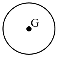 | Centre of ring | Outside the material |
| Circular Disc |
 | Geometric centre | Within the material |
| Solid Sphere |
 | Geometric centre | Within the material |
| Hollow Sphere |
 | Geometric centre | Outside the material |
| Solid Cylinder |
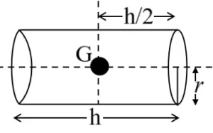 | Mid-point on the axis of cylinder | Within the material |
| Hollow Cylinder |
 | Mid-point on the axis of cylinder | Outside the material |
| Solid Cone |
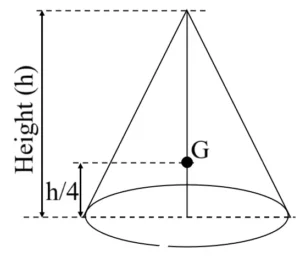 | At a height \(\frac{h}{4}\) from the base, on its axis | Within the material |
| Hollow Cone |
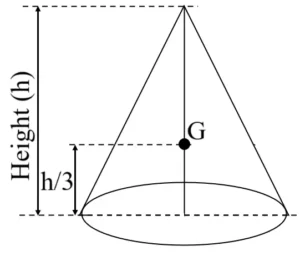 | At a height \(\frac{h}{3}\) from the base, on its axis | Outside the material |
| Triangular Lamina |
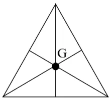 | The point of intersection of medians | Within the material |
| Parallelogram rectangular lamina |
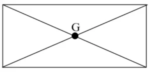 | The point of intersection of the diagonals | Within the material |
| Solid Cube or Cuboid |
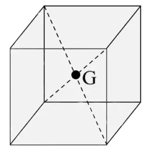 | The point of intersection of the diagonals | Within the material |
| Hollow Cube or Cuboid |
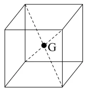 | The point of intersection of the diagonals | Outside the material |
Section C : Uniform Circular Motion
Uniform circular motion
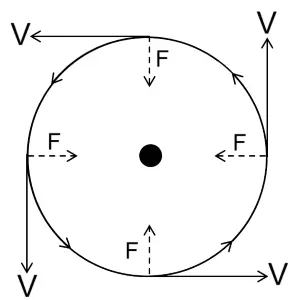
- Motion of a particle moving at a constant speed on a circular path, it’s motion is said to be uniform circular motion.
- In circular motion, the direction of motion is always along the tangent to the circular path at any point.
- In circular motion the direction of motion of the particles changes at each point.
- Speed remains constant in uniform circular motion, but velocity changes due to the continuous change in the direction of motion.
- The motion of a body which is moving with constant speed in a circular path is said to be accelerated because its velocity changes continuously due to the continuous change in the direction of motion.
- Centripetal force is required for circular motion.
- Example: Earth’s revolution around the sun.
Difference between uniform linear motion and uniform circular motion
| Uniform Linear Motion | Uniform Circular Motion |
| 1. The object moves along a straight path. | 1. The object moves along a circular path. |
| 2. Speed and direction both remains constant. | 2. Speed is constant but direction changes continuously. |
| 3. The velocity remains constant because both speed and direction are unchanging. | 3. The velocity changes continuously because the direction of motion keeps changing as the object moves along the circle. |
| 4. There is no acceleration since both speed and direction are constant. | 4. Accelerated motion due to continuous change in velocity and direction. |
| 5. Example: A car moving at constant speed on a straight road. | 5. Example: Earth moves around the Sun with a uniform velocity. |
Centripetal force
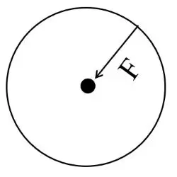
- Which force is required to move a body in a circular path with uniform speed, known as centripetal force. i.e., The force required for circular motion is centripetal force.
- The direction of centripetal force is always directed towards the centre of the circle.
- It is a real force.
Example :
- A planet moves around the sun in a nearly circular path.
- In an atom, an electron moves around the nucleus in a circular path due to centripetal force.
Centrifugal force
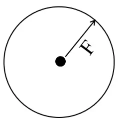
- Centrifugal force, a fictitious force, that is felt by an object moving in a curved path that acts outwardly away from the center of rotation.
- Centrifugal force is not a real force. It is a fictitious force.
Example :
- The children playing on a merry-go-round ride experience an outward force that tends to throw them on the outer side.
- Mud flying off the tyre.
***Note
The magnitude of the centripetal and the centrifugal force are equal but their direction are opposite to each other.
Differences between the centripetal and centrifugal force
| Centripetal force | Centrifugal force |
| 1. Force acts towards the centre of the circle. | 1. Force acts away from the centre of the circle. |
| 2. A real force | 2. A fictitious force |
Important Formulas for Class 10 ICSE Force
Students must memorize these formulas to solve numericals effectively.
- S.I. unit of force is \(Newton\ (N)\).
- \(1\ kgf\ =\ 9.8\ N\)
- S.I. unit of moment of couple is \(Newton\ meter\ (Nm)\).
- Torque \(=\ F\ \times\ ⊥ d\)
\(F_1\ \times\ d_1\ =\ F_2\ \times\ d_2\)
- \(1\ N\ =\ 10^5\ dyne\)
- \(1\ Nm\ =\ 10^7\ dyne\ cm\)
- \(Load\ \times\ Length\ of\ Load\ arm\ =\ Effort\ \times\ Length\ of\ Effort\ arm\)
- \(W_1\ \times\ l_1\ =\ W_2\ \times\ l_2\)
Download ICSE Class 10 Force Notes PDF
You can download simplified ICSE Physics Force Notes PDF including diagrams and key concepts for quick revision. These notes are useful for last-minute exam prep.
Tips to Master the Force Chapter
- Focus on conceptual clarity and diagrams.
- Practice numerical problems daily.
- Review all formulas and definitions regularly.
- Solve previous year ICSE Force Chapter Class 10 questions.
You can also visit :
| ICSE Class 10 Physics |
| ICSE Class 10 Chemistry |
| ICSE Class 10 Mathematics |
ICSE Class 10 Physics Notes
- ICSE Class 10 Physics Chapter 1 – Force Notes
- ICSE Class 10 Physics Chapter 2 – Work, Energy and Power Notes
- ICSE Class 10 Physics Chapter 3 – Machines Notes
- ICSE Class 10 Physics Chapter 5 – Refraction through Lens Notes Notes
- ICSE Class 10 Physics Chapter 7 – Sound Notes
- ICSE Class 10 Physics Chapter 8 – Current Electricity Notes
- ICSE Class 10 Physics Chapter 9 – Electrical Power and Household Circuits Notes
- ICSE Class 10 Physics Chapter 10 – Electro-magnetism Notes
- ICSE Class 10 Physics Chapter 11 – Calorimetry Notes
- ICSE Class 10 Physics Chapter 12 – Radioactivity Notes

