Introduction
ICSE Class 10 Physics Chapter 8 Current Electricity Notes are designed to help students understand the important concepts, formulas, laws and numerical problems included in the chapter. These notes are useful for ICSE Class 10 Board Exam preparation, revision and solving numerical problems.
Students can use these Current Electricity Class 10 ICSE Notes for quick revision and download the PDF for offline study.
Why Study Current Electricity?
Current Electricity is an important chapter for the ICSE Class 10 Physics examination. Students should focus on:
- Definitions and laws
- Important formulae
- Circuit diagrams
- Series and parallel combinations
- Numerical problems
- EMF and internal resistance
- Electrical power and energy
- Joule’s law
Study Support by Rohit Academy
Rohit Academy offers expert-curated ICSE Class 10 Physics Study Materials including ICSE Current Electricity Notes, diagrams, and key formulas for better understanding.
Study materials related to chapter 8: Current Electricity
To help you prepare the entire chapter thoroughly, explore the following study resources related to Chapter 8 Current Electricity:
Section (A) : Concept of Charge, Current, Potential, Potential Difference, and Resistance; Ohm’s Law
Concept of Charge
When two different materials are rubbed together, electrons may transfer from one body to another.
- A body that gains electrons becomes negatively charged.
- A body that loses electrons becomes positively charged.
- Like charges repel each other.
- Unlike charges attract each other.
- Charge is represented by Q or q.
- SI unit of charge: coulomb (C)
- 1 mC = 10–3 C, 1 μC = 10–6 C, 1 nC = 10–9 C
- Charge on an electron, e = –1.6 × 10⁻¹⁹ C
- 1 Coulomb = 6.25 × 10¹⁸ electrons
- Formula:
Q = ne
Where,- Q = total charge
- n = number of electrons
- e = charge of 1 electron (–1.6 × 10⁻¹⁹ C)
Electric Current
- The rate of flow of electric charges is called electric current.
Where,- I = Electric current
- Q = electric charge
- t = time
- It is a scalar quantity.
- SI unit of current: Ampere(A).
- Small units:
- mA = 10–3 A
- 1 μA = 10–6 A
- Current is measured with an ammeter, which is connected in series in the circuit (low resistance).
- 1 ampere = flow of 1 coulomb of charge per second through a conductor.
1 A = 1 Cs–1
Flow of Current
- In a metallic conductor, electrons move from the negative terminal towards the positive terminal.
- However, the conventional direction of current is taken from positive terminal to negative terminal.
- In metals → flow of free electrons.
- In electrolytes → movement of ions.
Concept of Potential and Potential Difference
Electric potential (V):
- Work done to bring a unit positive charge from infinity to a point.
- Unit: Volt (V)
Potential Difference (Vᴀ – Vʙ):
- Work done in moving a unit charge from one point to another.
Vᴀ – Vʙ = - Unit: Volt (V)
- One volt : When 1 joule of work is done in carrying 1 coulomb charge from one point to other, the potential difference is called 1 volt.
(1 V = 1 J/C) - Measured using a voltmeter, connected in parallel in a circuit (high resistance).
Ohm’s Law
- Ohm’s law states that if physical conditions and the temperature of the conductor remain constant, the current flowing through the conductor is directly proportional to the potential difference across its ends.
Where R is a constant and is known as Resistance of the conductor. - Limitation:
Valid only if temperature and physical conditions remain constant.
***Note:
- Current is directly proportional to potential difference.
If the potential difference is doubled, the current also gets doubled and if the potential difference is halved, the current also gets halved. - Current is inversely proportional to resistance.
If resistance is doubled, then current gets halved and if resistance halved, then current gets doubled. - If I = 1 A, then V = R
Concept of Resistance
- Resistance is the property of a conductor that opposes the flow of electric current through it.
- Formula:
- Unit: Ohm (Ω)
- One Ohm : When potential difference is 1 V and current through the circuit is 1 A, then resistance is said to be 1 ohm.
- 1 Ω
Causes of resistance:
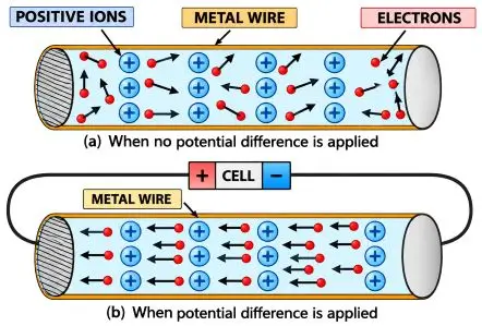
In a metal:
- There are many free electrons.
- Positive ions remain relatively fixed.
- Free electrons collide with positive ions while moving through the conductor.
- These collisions oppose the motion of electrons.
- This opposition gives rise to resistance.
Conductance
- The reciprocal of resistance is called resistance.
- Conductance
- Unit: ohm–1 (Ω–1)
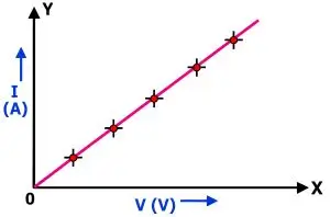
I–V graph:
- On an I–V graph (I on Y-axis, V on X-axis)
- Slope
- I–V graph is a straight line passing through the origin.
- Slope of I–V graph represents the reciprocal of resistance (conductance).

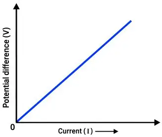
V–I Graph:
- On a V–I graph (V on Y-axis, I on X-axis)
- Slope
- V–I graph is a straight line through the origin for Ohmic materials.
- Slope of a V–I graph gives resistance.
Important Graph Rule:
- Steeper V–I graph → greater resistance.
- Steeper I–V graph → lower resistance.
Experimental Verification of Ohm’s Law
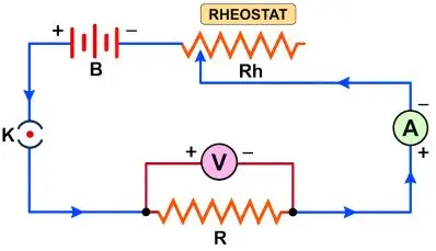
Apparatus: Battery, Rheostat, Ammeter, Voltmeter, Resistance wire, Key, Connecting wires.
Connections:
- Ammeter → series
- Rheostat → series
- Resistance wire → series
- Voltmeter → parallel across the resistance wire
Procedure:
- Close the key to complete the circuit.
- Adjust the rheostat to obtain a small current.
- Note the ammeter reading I.
- Note the voltmeter reading V.
- Gradually change the rheostat setting.
- Record different values of I and V.
- Calculate V/I for each observation.
- If V/I remains approximately constant, Ohm’s law is verified.
Ohmic and Non-Ohmic Resistors
Ohmic Resistors:
- Conductors that obey Ohm’s law are called ohmic resistors (or linear resistances).
- For an ohmic resistor: = constant
- Examples: Metallic conductors, Copper, Aluminium, Iron, Silver, Nichrome etc.
- Current–Voltage relationship of an ohmic resistor is shown in the below graph:
Characteristics of Ohmic Resistors:
- Obey Ohm’s law.
- V–I graph is a straight line.
- Resistance remains constant at constant temperature.
Non-Ohmic Resistors:
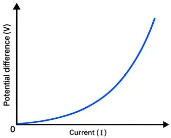
- Conductors that do not obey Ohm’s law are called non-ohmic resistors.
- For an non-ohmic resistor: constant
- Examples: LED, Junction diode, Filament of an electric bulb, Transistor, Solar cell etc.
- Current-Voltage relationship of non-ohmic resistors is shown in the graph below:
Characteristics of Non-Ohmic Resistors:
- Do not obey Ohm’s law.
- V–I graph is generally curved.
- Resistance changes with current or potential difference.
Differences between an ohmic and non-ohmic resistor
| Ohmic Resistors | Non-Ohmic Resistors |
| Obey Ohm’s law | Do not obey Ohm’s law |
| V-I graph is a straight line | V-I graph is curved |
| Resistance remains constant. | Resistance changes with voltage/current. |
| Examples: Copper, Nichrome | Examples: LED, filament bulb, diode |
Factors Affecting the Resistance of a Conductor
The resistance of a conductor depends on the following factors:
- Length of the Conductor (L):
- Resistance (R) ∝ length (L)
- Longer the wire → more resistance.
- Shorter wire → smaller resistance.
- Doubling the length doubles the resistance.
- Thickness (Area of cross-section, A)
- Resistance
- Thick wire → lower resistance.
- Thin wire → higher resistance.
- Doubling the wire radius reduces resistance to .
- Nature (Material) of the Conductor
- Good conductors (Ag, Cu, Pb, Al) have high free-electron concentration → low resistance.
- Insulators (rubber, glass, wood) have negligible free electrons → very high resistance
- Temperature of the Conductor
- Pure metals: Resistance increases with temperature (R ∝ T).
- Semiconductors: Resistance decreases with temperature.
- Alloys (Manganin, Constantan): Negligible change with temperature.
V-I graph for a conductor at two temperature:
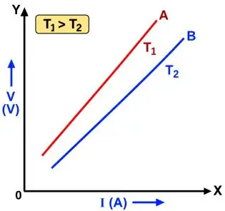
V–I graph at two temperatures l: At T₁ > T₂, the line is steeper (more resistance) at higher temperature T₁.
Specific Resistance (Resistivity)
Since we know that
…….(i)
…….(ii)
Combining (i) + (ii), we get
Where ρ (rho) is called specific resistance or resistivity.
- Definition: Resistivity is the resistance of a wire of that material having unit length and unit area of cross-section.
- Unit: ohm metre (Ω·m)
- Increasing order of resistivity: Metal < Semiconductor < Insulator
- Depends on:
- Nature of material
- Temperature
- Manganin and constantan are used to make standard resistors because they have high resistivity and show negligible effect of temperature on resistance.
- Resistivity is a characteristic property of a material.
- It does not depend on the length and area of cross-section (or radius) of the substance; it depends only on the nature of the material.
Typical values at 20°C:
| Substance | ρ (Ω·m) |
| Copper | 1.7 × 10⁻⁸ |
| Aluminium | 2.8 × 10⁻⁸ |
| Nichrome | 1.0 × 10⁻⁶ |
| Manganin | 4.4 × 10⁻⁷ |
Conductivity:
- The reciprocal of resistivity is called conductivity. It is represented by σ.
- SI Unit: ohm−1 metre−1 (Ω–1 m–1)
Choice of Material for a Wire:
| Purpose | Material | Reason |
| Connecting wires / Power transmission | Copper, Aluminium | Low resistivity; reduces energy loss. |
| Resistance wires | Manganin, Constantan | High resistivity and stable with temperature. |
| Fuse wire | Lead–tin alloy | Low melting point; melts during excess current. |
| Bulb filament | Tungsten | Very high melting point. |
| Heating elements | Nichrome | High resistivity; produces more heat. |
***Note:
Though silver has lower resistivity than copper, it is not used commercially due to high cost.
Superconductors
- A substance with zero resistance (infinite conductance) at very low temperature.
- Examples: Mercury (below 4.2 K), Lead (below 7.25 K), Niobium (below 9.2 K)
Section (B) : Electro-motive Force, Terminal Voltage and Internal Resistance of a Cell; Combination of Resistors
Electro-Motive Force (E.M.F.) of a Cell
- A cell consists of two electrodes immersed in an electrolyte.
- Chemical reactions inside the cell maintain a potential difference between the electrodes and convert chemical energy into electrical energy.
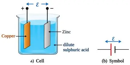
Example: Simple Cell
- Consists of zinc and copper electrodes dipped in dilute sulphuric acid (H2SO4).
- ions give electrons to zinc → Zinc becomes negative (cathode).
- ions take electrons from copper → Copper becomes positive (anode).
- Inside the cell, current flows from zinc to copper; in the external circuit, it flows from copper to zinc.
- E.M.F.: When no current is drawn from a cell (open circuit), the potential difference between its terminals is called its electro-motive force (e.m.f.).
- Denoted by ε (epsilon).
- Unit: volt (V)
- Measured using a high-resistance voltmeter connected across the cell.
- Formula:
Where,- ε = e.m.f. of the cell
- W = Total work done by the cell.
- q = charge moved
Factors Affecting E.M.F.
The E.M.F. of a cell depends on:
- Material of electrodes
- Nature and concentration of electrolyte
It does NOT depend on:
- Size or shape of electrodes
- Distance between electrodes
- Amount of electrolyte
Terminal Voltage of a Cell
- When current is drawn from a cell (closed circuit), the p.d. between the electrodes is called its terminal voltage.
- Formula :
Where:- V = terminal voltage
- W′ = Work done in the external circuit
- q = charge
- Unit : Volt (V)
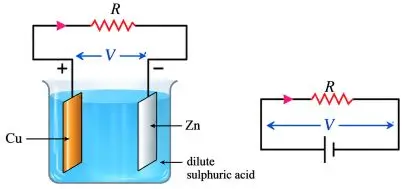
Voltage Drop in a Cell
- A cell has internal resistance due to its electrolyte.
- If w is the work done in moving charge q through the cell:
- v = voltage drop inside the cell.
By conservation of energy:
- W = W′ + w
- Dividing by q: W/q = W′/q + w/q
Therefore:
- ε = V + v
- V = ε − v
Hence: When a cell supplies current, its terminal voltage is less than its e.m.f.
Important Points
- When current flows, some energy is lost inside the cell due to internal resistance.
- Therefore, terminal voltage is always less than E.M.F. when cell is in use.
- The emf of the cell is equal to it’s terminal voltage when no current is drawn.
E.M.F. V/S Terminal Voltage
| E.M.F. | Terminal Voltage |
| Measured when no current is drawn from the cell. | Measured when current is drawn. |
| It is the energy supplied per unit charge by the cell. | It is the energy available per unit charge in the external circuit. |
| Independent of current drawn. | Depends on current drawn. |
| Equal to terminal voltage when cell is not supplying current. | Less than e.m.f. when cell supplies current. |
| Represented by ε. | Represented by V. |
Internal Resistance of a Cell (r)
- Definition: The resistance offered by the electrolyte to the flow of current is called the internal resistance of the cell.
- Reason: As current flows through the electrolyte, ions collide and oppose motion — causing a voltage drop inside the cell.
- Effect: It causes a voltage drop (I r) inside the cell, which is why the terminal voltage (V) is less than the E.M.F. (ε) when the cell is in use.
- Symbol: r
- SI unit: ohm (Ω)
Relationship between the emf, terminal voltage and internal resistance
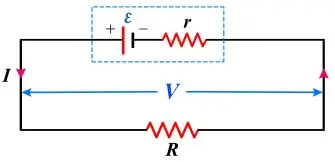
Suppose:
- e.m.f. of cell = ε
- Internal resistance = r
- External resistance = R
- Current flowing = I
- Total Resistance of the Circuit, RTotal = R + r
- Current drawn from the cell,
(by using ohm’s law) - EMF of cell, ε = I(R + r)
- Terminal voltage, V = IR
- Voltage drop inside the cell, V = Ir
- ε = V + v
or, V = ε − v - Internal Resistance,
Using,
Factors Affecting Internal Resistance
- Surface area of electrodes:
- Larger surface area ⟹ smaller internal resistance
- Distance between electrodes:
- More distance ⟹ more internal resistance
(r ∝ d)
- More distance ⟹ more internal resistance
- Concentration of electrolyte:
- Higher concentration / less ionisation ⟹ higher internal resistance.
- Temperature of electrolyte:
- High temperature ⟹ low internal resistance
Combination of Resistors
Resistors can be combined in three ways:
- Series
- Parallel
- both series and parallel
1. Resistors in Series Combination
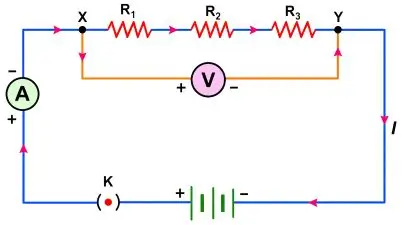
- Arrangement: Resistors joined one after another, so there is only one path for the current (I).
- Current (I) : Same current flows through each resistor.
I = I1 = I2 = I3 - Potential Difference (V) : Divided across resistors.
V = V1 + V2 + V3 - Equivalent Resistance (RS): The equivalent resistance is the sum of the individual resistances.
According to Ohm’s law,
V = IR
So, V = V1 + V2 + V3
IR = IR1 + IR2 + IR3
IR = I(R1 + R2 + R3)
RS = R1 + R2 + R3 - Note: Equivalent resistance (RS) in series is more than the largest individual resistance.
2. Resistors in Parallel Combination
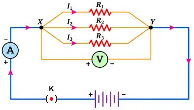
- Arrangement: In a parallel combination, one end of each resistor is connected to a common point, and all the other ends are connected to another common point.
- All resistors share the same voltage.
V = V1 = V2 = V3 - Current divides into branches.
I = I1 + I2 + I3 - Each resistor gets a separate current path.
- Equivalent Resistance (RP): The reciprocal of the equivalent resistance is the sum of the reciprocals of the individual resistances.
- Note: The equivalent resistance (RP) in parallel is less than the smallest resistor.
3. Series + Parallel Combination of Resistors
To solve a mixed circuit:
Step-by-Step Method:
- Identify which resistors are in series and which are in parallel.
- Simplify one part at a time:
- First simplify obvious series or parallel groups.
- Replace the simplified group with its equivalent resistance.
- Continue the process until the entire circuit reduces to one Req.
Series vs Parallel Combination
| Series | Parallel |
| Only one path for current | Multiple paths for current |
| Same current through each resistor | Current divides among branches |
| I = I1 = I2 = I3 | I = I1 + I2 + I3 |
| Voltage divides | Same voltage across each resistor |
| V = V1 + V2 + V3 | V = V1 = V2 = V3 |
| RS = R1 + R2 + R3 | |
| Equivalent resistance is greater than each individual resistance. | Equivalent resistance is less than the smallest resistance. |
V–I Graph for Series and Parallel Combinations
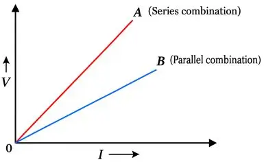
- Greater slope means greater resistance.
- The V–I graph for the series combination is steeper than that for the parallel combination.
Section (C) : Electrical Energy and Power
Electrical Energy
Electrical energy is the energy used by an electrical appliance when electric current flows through it.
According to the law of conservation of energy, it can neither be created nor destroyed but only converted from one form to another.
Examples of Energy Conversion
- Heating appliances (heater, geyser):
- Electrical energy → Heat energy
- Bulb filament:
- Electrical energy → Light + Heat
- Electric motor:
- Electrical energy → Mechanical energy
- Electrolysis (charging a battery):
- Electrical energy → Chemical energy
- Loudspeaker:
- Electrical energy → Sound energy
- Electromagnets:
- Electrical energy → Magnetic energy
Expressions for Electrical Energy

Where,
- E = Electrical Energy (in joule)
- V = voltage (in volt)
- I = current (in ampere)
- R = resistance (in ohm)
- t = time (in second)
- Q = charge (in coulomb)
❖ SI Unit of Electrical Energy: Joule (J)
ELECTRIC POWER
- Electric power is the electrical work done per unit time.
- SI unit of power: watt (W)
- 1 watt : one watt is defined as the power consumed when a current of 1 ampere flows through a potential difference of 1 volt.
1 Watt = 1 Volt × 1 Ampere = 1 Js–1
Bigger units:
- 1 kilowatt (kW) = 1000 W = 103 W
- 1 megawatt (MW) = 106 W
- 1 gigawatt (GW) = 109 W
Formula for calculating Electric Power
We know that,
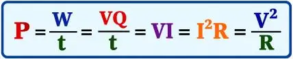
Where,
- P = Power (in watt)
- W = Energy consumed (in joule)
- V = Voltage (in volt)
- I = Current (in ampere)
- R = Resistance (in ohm)
- t = time (in second)
- Q = Electrical charge (in coulomb)
Electrical Energy and Power – Difference
| Electrical Energy | Electrical Power |
| Amount of electrical work/energy consumed. | Rate of consumption of electrical energy. |
| W = VIt | P = VI |
| SI unit: joule | SI unit: watt |
| Depends on time. | Does not directly include time. |
| W = Pt | P = W/t |
Power Rating of Electrical Appliances
- Electrical appliances are generally marked with their power rating and rated voltage.
- Electrical appliances are marked with ratings like “100 W – 220 V”.
- This means the appliance consumes 100 W of power at 220 V supply.
- Resistance of appliance (R) =
- Safe current (I) = PV
Important Point
- A bulb consumes power equal to its rated power only when connected at its rated voltage.
- If voltage is higher than rated → bulb glows brighter, consumes more power.
- If voltage is lower than rated → bulb glows dimmer (faint red), consumes less power.
Formula for calculating Electric Energy Consumed
E = Pt
Where:
- E = energy in kWh
- P = power in kW
- t = time in hours
- One watt-hour (1 Wh) : One watt-hour is the electrical energy consumed by a 1 W appliance operating for 1 hour.
- One kilowatt- hour (1 kWh) : One kilowatt-hour is the electrical energy consumed by a 1 kW appliance operating for 1 hour.
- Commercial / trade unit of electric energy consumed is kilowatt hour [kWh].
- Cost of Electrical Energy Consumed:
= Rate (per kWh) × Electrical energy (in kWh)
Relationship between 1 kWh and joule
HEATING EFFECT OF ELECTRIC CURRENT
- When an electric current passes through a high-resistance wire (such as nichrome), the wire becomes hot and produces heat. This phenomenon is known as the heating effect of electric current.
- The heat produced is given by Joule’s Law of Heating:
H = I2 Rt joule
Joule’s Law States That:
- Heat produced is directly proportional to the square of the current.
- Heat produced is directly proportional to the resistance of the wire.
- Heat produced is directly proportional to the time for which the current flows.
Important Points to Remember
- Doubling the current increases the heat produced to four times.
Halving the current reduces the heat to one-fourth. - Doubling the resistance doubles the heat produced.
Halving the resistance halves the heat produced. - Doubling the time for which current flows doubles the heat generated.
Halving the time halves the heat produced.
Other Forms of Joule’s Law
Applications of Heating Effect of Current
The heating effect of current is used in many electrical devices.
- Electric Heater:
A high-resistance heating element converts electrical energy into heat. - Electric Iron:
The heating element becomes hot and transfers heat to the iron plate. - Electric Toaster:
Electrical energy is converted into heat for toasting bread. - Electric Kettle:
Electrical energy is converted into heat to heat water. - Electric Oven:
The heating element produces heat for cooking. - Fuse:
The heating effect causes the fuse wire to melt when excessive current flows, protecting the circuit. - Electric Bulb:
The filament becomes extremely hot and glows, producing light along with heat.
Important Current Electricity Formulas for ICSE Class 10
| Physical Quantities | Units |
| Electric Charge (Q) | Coulomb (C) |
| Potential difference (V) | volt (V) |
| Electric current (I) | Ampere (A) |
| Resistance (R) | ohm (Ω) |
| Resistivity (ρ) | ohm-metre (Ω-m) |
| Work / Energy (E) | Joule (J) |
| Power (P) | watt (W) |
| Quantity | Formula |
| Charge | Q = ne |
| Current | |
| Potential difference | |
| Ohm's law | V = IR |
| Resistance | |
| Specific resistance / resistivity | |
| Series resistance | RS = R1 + R2 + R3 |
| Parallel resistance | |
| Electrical Energy | |
| Power | |
| Electrical energy | E = Pt |
| Heat produced | |
| EMF | |
| Terminal voltage | V = ε − Ir |
| Voltage Drop | |
| Internal Resistance | v = Ir |
Download ICSE Class 10 Physics Current Electricity Notes PDF
Students can use these ICSE Class 10 Physics Chapter 8 Current Electricity Notes for quick revision and board examination preparation. The notes include important concepts, definitions, formulae and numerical topics in a simple and easy-to-understand format.
Download the Current Electricity PDF and use it for revision before your ICSE Class 10 Physics examination.
Conclusion
These ICSE Class 10 Current Electricity Notes provide a concise revision resource covering the major concepts, laws and formulae of the chapter. Regular practice of numerical problems and important questions can help students strengthen their understanding of Current Electricity.
You can also visit:
ICSE Class 10 Physics Notes
| ☛ ICSE Class 10 Physics Chapter 1 – Force Notes |
| ☛ ICSE Class 10 Physics Chapter 2 – Work, Energy and Power Notes |
| ☛ ICSE Class 10 Physics Chapter 3 – Machines Notes |
| ☛ ICSE Class 10 Physics Chapter 4 – Refraction of Light at Plane Surfaces Notes |
| ☛ ICSE Class 10 Physics Chapter 5 – Refraction through Lens Notes |
| ☛ ICSE Class 10 Physics Chapter 6 – Spectrum Notes |
| ☛ ICSE Class 10 Physics Chapter 7 – Sound Notes |
| ☛ ICSE Class 10 Physics Chapter 8 – Current Electricity Notes |
| ☛ ICSE Class 10 Physics Chapter 9 – Electrical Power and Household Circuits Notes |
| ☛ ICSE Class 10 Physics Chapter 10 – Electro-magnetism Notes |
| ☛ ICSE Class 10 Physics Chapter 11 – Calorimetry Notes |
| ☛ ICSE Class 10 Physics Chapter 12 – Radioactivity Notes |
Official Website:
Students can visit the official CISCE website for more details and updates.