Machines Class 10 Physics PYQs
Are you preparing for the ICSE Class 10 Physics examination and looking for ICSE Class 10 Physics Chapter 3 Machines Previous Year Questions? Practising questions from previous examinations is an effective way to understand the question pattern, identify important concepts and improve numerical-solving skills.
This collection of ICSE Class 10 Physics Machines Previous Year Questions covers important concepts such as mechanical advantage, velocity ratio, efficiency, levers, pulleys, inclined planes and the principle of moments.
Why Practise Machines Previous Year Questions?
Solving ICSE Class 10 Physics Chapter 3 Machines Previous Year Questions helps students become familiar with the type and difficulty of questions asked in the examination.
Regular practice can help you:
- Understand the ICSE question pattern
- Identify frequently tested concepts
- Revise important formulas
- Improve numerical-solving skills
- Practise diagram-based questions
- Manage examination time effectively
- Build confidence before the board examination
Study Support by Rohit Academy
Rohit Academy offers expert-curated ICSE Class 10 Physics Study Materials including ICSE Machines Previous Year Questions, diagrams, and key formulas for better understanding.
Study materials related to chapter 3: Machines
To help you prepare the entire chapter thoroughly, explore the following study resources related to Chapter 3 Machine:
| ☛ ICSE Class 10 Chapter 3 Machines Ex 3(A) Solutions |
| ☛ ICSE Class 10 Chapter 3 Machines Ex 3(B) Solutions |
| ☛ ICSE Class 10 Physics Chapter 3 – Machines Notes |
ICSE Class 10 Physics – Machines: Previous Year Questions
Question 1
Which class of levers has a mechanical advantage always greater than one? What change can be brought about in this lever to increase its mechanical advantage? [ICSE 2007]
Answer:
A second-order lever always has a mechanical advantage greater than one.
Its mechanical advantage can be increased by increasing the length of the effort arm, i.e. by moving the effort farther away from the fulcrum.
Question 2
Write an expression to show the relationship between mechanical advantage, velocity ratio and efficiency for a simple machine. [ICSE 2007]
Answer:
Efficiency, η = × 100%
Question 3
A block and tackle pulley system has a velocity ratio 3.
(i) Draw a labelled diagram of this system. In your diagram, indicate clearly the points of application and the directions of the load and effort.
(ii) Why should the lower block of this pulley system be of negligible weight ? [ICSE 2007]
Answer:
(i) Given,
V.R = n (number of pulleys) = 3
Hence, number of pulleys = 3 The labelled diagram below shows the arrangement of the pulley system, clearly indicating the points of application and the directions of the load (L) and effort (E).
For a V.R. = 3, there are three supporting strands of the rope.
(ii) The lower block should be of negligible weight so that almost all the effort is used to lift the load and not to lift the weight of the lower block itself.
Question 4
Copy the diagram of the forearm given below, indicate the positions of Load, Effort and Fulcrum. [ICSE 2008]
Answer:
The positions of load L, effort E and fulcrum F in the forearm are shown below: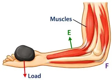
It is a Class III lever.
Question 5
(i) Draw a labelled diagram of a block and tackle system of pulleys with two pulleys in each block. Indicate the directions of the load, effort and tension in the string.
(ii) Write down the relation between the load and the effort of the pulley system. [ICSE 2008]
Answer:
(i) A pulley system with two pulleys in each block.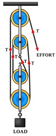
(ii) Relation between L and E:
E = T
Since four strands support the load:
L = 4T
Therefore,
L = 4E
Hence, M.A. = 4.
Question 6
(i) With reference to the terms mechanical advantage, velocity ratio and efficiency of a machine, name the term that will not change for a machine of a given design.
(ii) Define the term stated by you in part (i). [ICSE 2009]
Answer:
(i) The velocity ratio will not change.
(ii) Velocity ratio is defined as the ratio of the velocity of effort to the velocity of the load.
Velocity Ratio
Question 7
A pulley system comprises two pulleys, one fixed and the other movable.
(i) Draw a labelled diagram of the arrangement and show clearly the directions of all the forces acting on it.
(ii) What change can be made in the movable pulley of this system to increase the mechanical advantage of the system. [ICSE 2009]
Answer:
(i) Below is the diagram of an arrangement of two pulleys, one fixed and other moveable: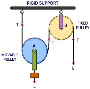
(ii) To increase the mechanical advantage of this system, add more movable pulleys to the arrangement.
Question 8
(i) Why is the mechanical advantage of a lever of the second order always greater than one ?
(ii) Name the type of single pulley that has a mechanical advantage greater than one. [ICSE 2010]
Answer:
(i) In a second-order lever, the load lies between the fulcrum and the effort. Therefore, the effort arm is always longer than the load arm.
M.A. > 1
Hence, its mechanical advantage is always greater than one.
(ii) Single movable pulley.
Question 9
(i) Write a relation expressing the mechanical advantage of a lever.
(ii) Write an expression for the mechanical advantage of an inclined plane.
(iii) Give two reasons as to why the efficiency of a single movable pulley system is always less than 100%. [ICSE 2010]
Answer:
(i) M.A =
(ii) M.A. =
(iii) The efficiency of a single movable pulley system is not 100% because of the following reasons:
- There is friction in the pulley bearings or at the axle.
- The weight of the pulley and string is not zero.
Question 10
Name a machine which can be used to:
(i) multiply force
(ii) change the direction of force applied. [ICSE 2011]
Answer:
(i) Single movable pulley
(ii) Single fixed pulley
Question 11
The diagram below shows a lever in use.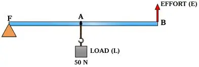
(i) To which class of lever does it belong ?
(ii) If FA = 40 cm, AB = 60 cm, then find the mechanical advantage of the lever. [ICSE 2011]
Answer:
(i) Class 2 lever
(ii) Given,
● FA = 40 cm
● AB = 60 cm
Therefore,
FB = FA + AB = 40 + 60 = 100 cm
Mechanical Advantage:
⇒ M.A. =
⇒ M.A. =
⇒M.A. =
⇒ M.A. = 2.5
Question 12
(i) What is meant by an ideal machine?
(ii) Write a relationship between the mechanical advantage (M.A.) and velocity ratio (V.R.) of an ideal machine. [ICSE 2011]
Answer:
(i) An ideal machine is a machine in which there is no loss of energy due to friction, weight of moving parts, etc.
(ii) For an ideal machine:
M.A. = V.R.
Question 13
(i) State the class of levers and the relative positions of load (L), effort (E) and fulcrum (F) in each of the following cases :
(a) A bottle opener.
(b) Sugar tongs.
(ii) Why is less effort needed to lift a load over an inclined plane as compared to lifting the load directly? [ICSE 2012]
Answer:
(i)
(a) Bottle opener: A bottle opener is a Class II lever because the fulcrum (F) and effort (E) are at the two ends, with the load (L) lying between them.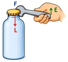
(b) Sugar tongs: Sugar tongs are a Class III lever because the fulcrum (F) and load (L) are at the two ends, with the effort (E) lying between them.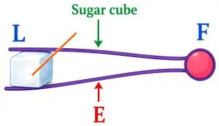
(ii) An inclined plane allows the load to be lifted through a longer distance using a smaller force. Therefore, less effort is needed than lifting the load vertically.
Question 14
A coolie is pushing a box weighing 1500 N up an inclined plane 7.5m long on to a platform, 2.5 m above the ground.
(i) Calculate the mechanical advantage of the inclined plane.
(ii) Calculate the effort applied by the coolie.
(iii) In actual practice, the coolie needs to apply more effort than what is calculated. Give one reason why you think the coolie needs to apply more effort. [ICSE 2013]
Answer:
Given,
- Load (L) = 1500 N
- Length of inclined plane (l) = 7.5 m
- Height of inclined plane (h) = 2.5 m
(i) Mechanical Advantage (M.A.)
M.A.
(ii) M.A. =
⇒ 30 =
⇒ E = 500 N
(iii) More effort is required because of friction.
Question 15
A type of single pulley is very often used as a machine even though it does not give any gain in mechanical advantage.
(i) Name the type of pulley used.
(ii) For what purpose is such a pulley used? [ICSE 2013]
Answer:
(i) Single fixed pulley
(ii) It is used to change the direction of the effort.
Question 16
(i) In what way does an ‘Ideal machine’ differ from a ‘Practical machine’ ?
(ii) Can a simple machine act as a force multiplier and a speed multiplier at the same time ? [ICSE 2013]
Answer:
(i) Difference:
| Ideal machine | Practical machine |
| No energy loss | Some energy is lost |
| Efficiency = 100% | Efficiency < 100% |
| M.A. = V.R. | M.A. < V.R. |
| Friction is absent | Friction is present |
(ii) No. A machine cannot act as both simultaneously.
Question 17
Which class of lever found in the human body is being used by a boy :
(i) When he holds a load on the palm of his hand.
(ii) When he raises the weight of his body on his toes ? [ICSE 2013]
Answer:
(i) Raising a load on the palm: Class III lever
Explanation: The elbow acts as the fulcrum, the biceps provides the effort between the elbow and the load in the palm.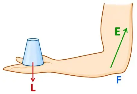
(ii) Raising the weight of body on toes: Class II lever
Explanation: The toes act as the fulcrum, body weight acts as the load, and the calf muscles provide the effort.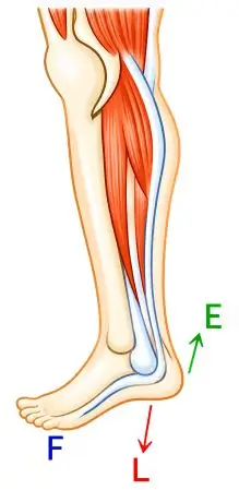
Question 18
A block and tackle system of pulleys has a velocity ratio 4.
(i) Draw a labelled diagram of the system indicating clearly the points of application and directions of load and effort.
(ii) What is the value of the mechanical advantage of the given pulley system if it is an ideal pulley system ? [ICSE 2013]
Answer:
(i) Labelled diagram of the system with direction and points of application of load and effort marked is shown below:
(ii) We know,
M.A. =
Here,
Load = 4T
Effort = T
Therefore,
M.A. =
M.A. = 4
Hence, M.A. = 4
Question 19
What is the principle of an ideal machine? [ICSE 2014]
Answer:
The principle of an ideal machine is that the work done by the effort is equal to the work done on the load.
Question 20
Draw a diagram to show how a single pulley can be used so as to have its ideal M.A = 2. [ICSE 2014]
Answer:
Single movable pulley.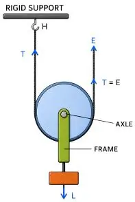
Here, the load is supported by two tensions.
L = T + T = 2T
E = T
Therefore,
M.A. =
M.A. = = 2
Hence, the ideal mechanical advantage of a single movable pulley is 2.
Question 21
Derive a relationship between mechanical advantages, velocity ratio and efficiency of a machine. [ICSE 2014]
Answer:
Suppose a machine overcomes a load L by applying an effort E.
Let:
- Displacement of effort = dE
- Displacement of load = dL
Work input = Effort × displacement of effort Work input = E × dE
Work output = Load × displacement of load
Work output = L × dL
Efficiency of the machine is given by:
η =
Therefore,
η =
Rearranging,
η =
We know that:
M.A. =
and
V.R. =
Therefore,
Hence,
η =
Therefore,
M.A. = η × V.R.
If efficiency is expressed as a percentage:
M.A.
Hence, the mechanical advantage of a machine is equal to the product of its efficiency and velocity ratio.
M.A. = Efficiency × V.R.
Question 22
A scissor is a ………… multiplier. [ICSE 2015]
Answer:
Force multiplier
Question 23
Draw a simplified diagram of a lemon crusher, indicating direction of load and effort. [ICSE 2015]
Answer:
Labelled diagram of lemon crusher is shown below: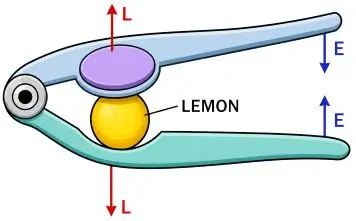
Question 24
A block and tackle system has V.R = 5.
(i) Draw a neat labelled diagram of a system indicating the direction of its load and effort.
(ii) Rohan exerts a pull of 150 Kgf. What is the maximum load he can raise with this pulley system if its efficiency = 75% ? [ICSE 2015]
Answer:
Given,
- V.R. = 5
- Effort (E) = 150 kgf
- Efficiency = 75%
(i) A block and tackle system with V.R. = 5 has five supporting strands.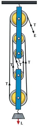
(ii) Efficiency = × 100
⇒ 75 = × 100
⇒ M.A. = 3.75
Now,
M.A. =
⇒ 3.75 =
⇒ L = 562.5 kgf
∴ Maximum load = 562.5 kgf.
Question 25
Give the expression for mechanical advantage of an inclined plane in terms of the length of an inclined plane. [ICSE 2015]
Answer:
Mechanical advantage of an inclined plane:
M.A.
Question 26
With reference to the terms Mechanical Advantage, Velocity Ratio and efficiency of a machine, name and define the term that will not change for a machine of a given design. [ICSE 2016]
Answer:
The velocity ratio will not change.
Definition:
Velocity ratio is defined as the ratio of the velocity of effort to the velocity of the load.
Velocity Ratio =
Question 27
From the diagram given below, answer the questions that follow: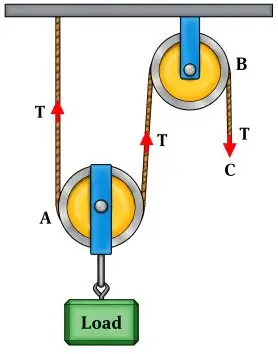
(i) What kind of pulleys are A and B ?
(ii) State the purpose of pulley B.
(iii) What effort has to be applied at C to just raise the load L = 20 kgf ? [ICSE 2016]
(Neglect the weight of pulley A and friction).
Answer:
(i) A is a movable pulley and B is a fixed pulley.
(ii) Pulley B is used to change the direction of the effort, i.e. in the downward direction.
(iii) Given,
Load (L) = 20 kgf
M.A. = 2
Using the relation:
M.A. =
Substituting the values:
2 =
Therefore,
E =
E = 10 kgf
Hence, the effort required = 10 kgf.
Question 28
(i) An effort is applied on the bigger wheel of a gear having 32 teeth. It is used to turn a wheel of 8 teeth. Where is it used ?
(ii) A pulley system has three pulleys. A load of 120N is overcome by applying an effort of 50N.
Calculate the Mechanical Advantage and Efficiency of this system. [ICSE 2016]
Answer:
(i) The gear arrangement is used as a speed multiplier.
(ii) Given:
- Load (L) = 120 N
- Effort (E) = 50 N
- V.R. = 3
Mechanical Advantage:
M.A. =
M.A. =
M.A. = 2.4
Efficiency:
Efficiency = × 100
= × 100
= 80%
Therefore,
- M.A. = 2.4
- Efficiency = 80%
Question 29
Which class of lever will always have MA > 1 and why? [ICSE 2017]
Answer:
A class II lever always has M.A. > 1 because the effort arm is always longer than the load arm.
Question 30
A boy uses a single fixed pulley to lift a load of 50 kgf to some height. Another boy uses a single movable pulley to lift the same load to the same height. Compare the effort applied by them. Give a reason to support your answer. [ICSE 2017]
Answer:
First boy using a single fixed pulley:
Effort = 50 kgf
For a single movable pulley:
Effort = = 25 kgf
Therefore, the second boy applies less effort.
Reason: A single fixed pulley has M.A. = 1, while an ideal single movable pulley has M.A. = 2.
Question 31
A pulley system with VR = 4 is used to lift a load of 175 kgf through a vertical height of 15 m. The effort required is 50 kgf in the downward direction, (g = 10 N kg–1).
Calculate:
(i) Distance moved by the effort.
(ii) Work done by the effort.
(iii) M.A. of the pulley system.
(iv) Efficiency of the pulley system. [ICSE 2017]
Answer:
Given:
- V.R. = 4
- Load (L) = 175 kgf
- Effort (E) = 50 kgf
- Height moved by load = 15 m
- g = 10 N kg–1
(i) V.R.
⇒
⇒ dE = 4 × 15 = 60 m
(ii) Work = Effort × Distance
⇒ Work = 50 × 60
⇒ Work = 3000 kgf m
⇒ Work = 30,000 J
(iii) M.A. =
⇒ M.A. =
⇒ M.A. = 3.5
(iv) Efficiency = × 100
Efficiency = × 100
Efficiency = 87.5%
Question 32
The diagram below shows a lever in use:
(i) To which class of levers does it belong?
(ii) Without changing the dimensions of the lever, if the load is shifted towards the fulcrum what happens to the mechanical advantage of the lever? [ICSE 2018]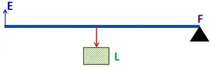
Answer:
(i) The diagram represents a Class II lever because the load lies between the fulcrum and the effort.
(ii) The mechanical advantage increases when the load is shifted towards the fulcrum because the load arm decreases. As a result, less effort is required to lift the load.
Question 33
(i) Draw a diagram to show a block and tackle pulley system having a velocity ratio of 3 marking the direction of load(L), effort(E) and tension(T).
(ii) The pulley system drawn lifts a load of 150 N when an effort of 60 N is applied. Find its mechanical advantage.
(iii) Is the above pulley system an ideal machine or not? [ICSE 2018]
Answer:
(i) The block and tackle pulley system with a velocity ratio of 3 is shown below, with the directions of the load (L), effort (E) and tension (T) clearly marked.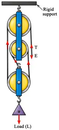
(ii) Given,
L = 150 N
E = 60 N
Mechanical Advantage (M.A.) = = = 2.5
(ii) Since M.A. ≠ V.R., the pulley system is not an ideal machine.
Question 34
The diagram below shows a pulley arrangement:-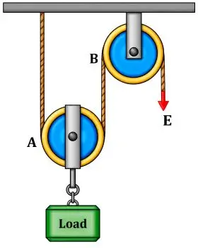
(i) Copy the diagram and mark the direction of tension on each strand of the string.
(ii) What is the velocity ratio of the arrangement?
(iii) If the tension acting on the string is T, then what is the relationship between T and effort E?
(iv) If the free end of the string moves through a distance x, find the distance by which the load is raised. [ICSE 2019]
Answer:
(i) The direction of tension (T) is marked in the diagram.
(ii) V.R. =
⇒ V.R. = 2
(iii) The effort E balances the tension.
Therefore, T = E
(iv) V.R.
Therefore,
Distance moved by load =
Hence, the load moves through a distance of .
Question 35
The diagram below shows a claw hammer used to remove a nail: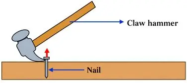
(i) To which class of lever does it belong ?
(ii) Give one more example of the same class of lever mentioned by you in (i) for which the mechanical advantage is greater than one. [ICSE 2019]
Answer:
(i) A claw hammer is an example of a Class I lever.
(ii) Another example of a Class I lever is shears, which are used to cut metal sheets.
Question 36
(i) Identify the class of the lever shown in the diagram below: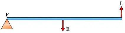
(ii) How is it possible to increase the M.A. of the above lever without increasing its length. [ICSE 2020]
Answer:
(i) The lever shown in the diagram is a Class III lever.
(ii) Its mechanical advantage can be increased by moving the effort E away from the fulcrum, thereby increasing the length of the effort arm.
Question 37
(i) A block and tackle system of pulleys has velocity ratio 4. Draw a neat Labelled diagram of the system indicating clearly the points of appliance and direction of load and effort.
(ii) What will be its V.R. if the weight of the movable block is doubled? [ICSE 2020]
Answer:
(i) The labelled diagram of the system is shown below, with the directions and points of application of the load (L) and effort (E) clearly marked.
(ii) The increase in the weight of the movable block does not affect the velocity ratio. Therefore, V.R. = 4.
Question 38
Choose the correct answer:-
A woman draws water from a well using a fixed pulley. The mass of the bucket and the water together is 10 kg. The force applied by the woman is 200 N. The mechanical advantage is: (g = 10 m/s2) [ICSE 2021 Sem 1]
(a) 2
(b) 20
(c) 0.05
(d) 0.5
Answer:
(d) 0.5
Explanation:
Given:
Mass = 10 kg, g = 10 m/s2, Effort = 200 N
Load = 10 × 10 = 100 N
M.A. = = = 0.5
Question 39
Choose the correct answer:-
A single fixed pulley is used because:
(a) it changes the direction of applied effort conveniently.
(b) it multiplies speed.
(c) it multiplies effort.
(d) its efficiency is 100%. [ICSE 2021 Sem 1]
Answer:
(a) It changes the direction of applied effort conveniently
Question 40
Choose the correct answer:-
In the diagram shown below, the velocity ratio of the arrangement is: [ICSE 2021 Sem 1]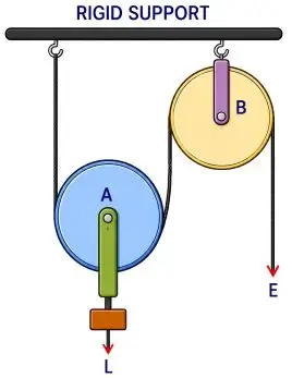
(a) 1 (b) 2
(c) 3 (d) 0
Answer:
(b) 2
Explanation:
The arrangement has one movable pulley (B) and one fixed pulley (A).
For a single movable pulley:
V.R. =
Therefore,
V.R. = 2.
Question 41
(i) Name a single pulley in which displacement of load and effort is not the same.
(ii) State one advantage of this pulley. [ICSE 2023]
Answer:
(i) A single movable pulley.
(ii) It acts as a force multiplier, reducing the effort required to lift a load.
Question 42
A block and tackle system of pulleys has velocity ratio 4.
(a) Draw a labelled diagram of the system indicating clearly, the direction of the load and the effort.
(b) What is the value of the mechanical advantage of the given pulley system if it is an ideal pulley system? [ICSE 2023]
Answer:
(a) A block and tackle system with V.R. = 4 has four supporting strands.
(b) For an ideal machine:
M.A. = V.R.
Therefore,
M.A. = 4
Question 43
Choose the correct answer:-
Which of the following is a class III lever?
(a) Pair of scissors (b) Wheelbarrow
(c) Crowbar (d) Human forearm [ICSE 2024]
Answer:
(d) Human forearm
Explanation:
The human forearm is a Class III lever because the effort acts between the fulcrum and the load.
Question 44
Name the class of the lever shown in the picture below: [ICSE 2024]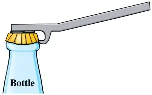
Answer:
CLass II lever
Question 45
Meera chose to use a block and tackle system of ‘9’ pulleys instead of a single movable pulley to lift a heavy load.
(a) What is the advantage of using a block and tackle system over a single movable pulley?
(b) Why should she connect more number of pulleys in the upper fixed block? [ICSE 2024]
Answer:
(a) The main advantage of a block and tackle system is that it provides a greater mechanical advantage, so a smaller effort is required to lift a heavy load.
(b) More pulleys should be connected in the upper fixed block so that the pulleys can be arranged properly and the effort can be applied conveniently in the downward direction.
Question 46
Given are two pulleys. [ICSE 2024]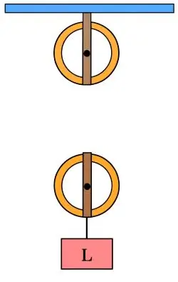
(a) Copy and complete the labelled diagram connecting the two pulleys with a tackle to obtain Velocity Ratio = 2.
(b) If Load = 48 kgf and efficiency is 80% then
Calculate:
- Mechanical Advantage.
- Effort needed to lift the load.
Answer:
(i) The diagram is given below: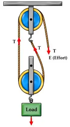
(ii) Given:
- Load (L) = 48 kgf
- Efficiency = 80%
- V.R. = 2
1. Mechanical Advantage:
Efficiency = × 100
⇒ 80 = × 100
⇒ M.A. = 1.6
2. Effort:
M.A. =
⇒ 1.6 =
⇒ E =
⇒ E = 30 kgf
Question 47
Choose the correct answer:-
For a lever, a graph is plotted with load on Y-axis and effort on X-axis. Which of the following represents the slope of the graph? [ICSE 2025]
(a) Mechanical advantage
(b) Velocity ratio
(c)
(d)
Answer:
(a) Mechanical Advantage (M.A.)
Explanation:
In a load–effort graph, the slope is:
Slope = = Mechanical Advantage.
Question 48
Three levers X, Y, Z of equal lengths are shown in the diagram. 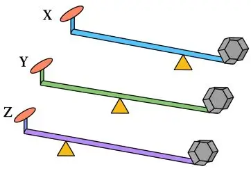
(a) Which class of lever do these belong to?
(b) Among these (X, Y or Z) which one will give the maximum mechanical advantage? Justify your answer. [ICSE 2025]
Answer:
(a) All are Class I levers because the fulcrum lies between the load and the effort.
(b) We know that:
Mechanical Advantage =
For X, the effort arm is greater than the load arm. Hence, X has the maximum mechanical advantage.
Question 49
Draw a block and tackle system of pulleys with velocity ratio equal to 3. [ICSE 2025]
Answer:
The diagram is given below:
Question 50
Choose the correct answer:-
The Velocity Ratio (VR) of a block and tackle system of two pulleys with the effort in the upward direction is: [ICSE 2026]
(a) 1 (b) 2
(c) 3 (d) 4
Answer:
(c) 3
Explanation:
For a block and tackle system with 2 pulleys and the effort in the upward direction:
V.R. = n + 1
V.R. = 2 + 1 = 3.
Question 51
Case 1: Lata cuts a potato into two halves, using a cutter which belongs to a Class II lever. She needed effort E1.
Case 2: Then she cuts one half of this potato again, but this time she needed effort E2. If E1 > E2 then:
(a) In which case (1st or 2nd) was the potato closer to her hand applying the effort? (Assume normal reaction of the surface of the potato is same in both cases)
(b) Give a reason for your answer in (a) above. [ICSE 2026]
Answer:
(a) The potato was closer to her hand in Case 1.
(b) For a Class II lever:
E × Effort arm = L × Load arm
Since the load and effort arm are the same in both cases, greater effort means a greater load arm. Hence, in Case 1, the potato was closer to the effort.
Question 52
To which class of lever does a pair of scissors belong? [ICSE 2026]
Answer:
A pair of scissors is a Class I lever because the fulcrum lies between the load and effort.
Question 53
To lift a load of 30 kgf, Suhas uses a single fixed pulley while Radha uses a single movable pulley. The displacement of efforts in both the cases are equal. In an ideal situation calculate the ratio of :
(a) the efforts in the two cases.
(b) the potential energy gained by the loads in the two cases.
(c) the efficiencies in the two cases. [ICSE 2026]
Answer:
Given,
Load = 30 kgf
(a) Ratio of efforts:
Mechanical advantage (M.A.) is given by:
M.A. =
For a single fixed pulley:
M.A. = 1
Therefore,
E1 =
E1 =
E1 = 30 kgf
For a single movable pulley:
M.A. = 2
Therefore,
E2 =
E2 =
E2 = 15 kgf
Hence,
E1 : E2 = 30 : 15 = 2 : 1
∴ Ratio of efforts = 2 : 1
(b) Potential energy gained = Load × height raised
Let the height raised by the load in the fixed pulley be h.
For the same effort displacement:
In a fixed pulley, the load rises through h.
In a movable pulley, the load rises through .
Therefore,
PE1 : PE2 = (30 × h) : (30 × h/2)
PE1 : PE2 = 2 : 1
∴ Ratio of potential energies = 2 : 1
(c) For an ideal machine, Efficiency = 100%
Both pulleys are considered ideal.
Therefore,
Efficiency ratio = 100 : 100 = 1 : 1
∴ Ratio of efficiencies = 1 : 1
Download Machines Previous Year Questions PDF
Use this collection of ICSE Class 10 Physics Chapter 3 Machines Previous Year Questions for systematic examination preparation. Practise the questions repeatedly, revise the important formulas and focus on understanding the concepts.
You can also visit:
ICSE Class 10 Physics Important Previous Year Questions
| ☛ Chapter 1 – Force Previous Year Questions |
| ☛ Chapter 2 – Work, Energy and Power Previous Year Questions |
| ☛ Chapter 3 – Machines Previous Year Questions |
| ☛ Chapter 4 – Refraction of Light at Plane Surfaces Previous Year Questions |
| ☛ Chapter 5 – Refraction through Lens Previous Year Questions |
| ☛ Chapter 6 – Spectrum Previous Year Questions |
| ☛ Chapter 7 – Sound Previous Year Questions |
| ☛ Chapter 8 – Current Electricity Previous Year Questions |
| ☛ Chapter 9 – Electrical Power and Household Circuits Previous Year Questions |
| ☛ Chapter 10 – Electro-magnetism Previous Year Questions |
| ☛ Chapter 11 – Calorimetry Previous Year Questions |
| ☛ Chapter 12 – Radioactivity Previous Year Questions |
Official Websites